Product Overview
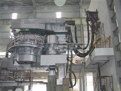
A Submerged Arc Furnace (SAF) is an industrial electric smelting system used for high-temperature reduction and melting of mineral feedstocks, metal oxides, and carbonaceous reducing agents. The process uses carbon or graphite electrodes immersed in the burden to transfer electrical energy into the furnace through resistive heating and localized electric arcs.
SAF systems can be configured for ferroalloy, silicon metal, calcium carbide, and other high-temperature smelting processes.
Reference Transformer Capacity: 5 to 120 MVA
Operating Temperature Range: 1,500 degrees C to above 2,000 degrees C
Furnace Shell Configurations: Circular or rectangular variants
Electrode Systems: Self-baking Soderberg or prebaked carbon/graphite electrodes
Core Outputs: Ferrosilicon (FeSi), silicomanganese (SiMn), ferrochrome (FeCr), ferronickel (FeNi), silicon metal, and calcium carbide
-
![High Titanium Slag Smelting Furnace]() High Titanium Slag Smelting Furnace1.Engineered with high-capacity DC/AC transformers to maintain stable smelting temperatures above 1,700°C, ensuring optimal phase separation between titanium slag and pig iron.2.Features high-density
-
![Rare Metal Melting Furnace]() Rare Metal Melting Furnace1.Equipped with high-performance vacuum pumping systems and leak-tight chambers to prevent interstitial contamination (O, N, H) of reactive metals.2.Utilizes Vacuum Arc Remelting (VAR) or Plasma Arc
-
![Refractory Metal Melting Furnace]() Refractory Metal Melting Furnace1.Engineered with Electron Beam (EB) or Vacuum Arc Remelting (VAR) technology to sustain stable temperatures above 3,500°C for refractory metals like Tungsten and Tantalum.2.Features a
-
![Ferronickel Furnace]() Ferronickel Furnace1.Engineered with 60-120 MVA transformers and deep submerged arc technology to maintain stable melt temperatures above 1,600°C for efficient laterite ore processing.2.Features an integrated copper
-
![DC Ferrosilicon Furnace]() DC Ferrosilicon Furnace1.Achieves a high power factor (>0.95) through DC technology, reducing specific energy consumption by 5-10% compared to conventional AC units.2.Eliminates proximity and skin effects common in AC
-
![Ferrosilicon Smelting Furnace]() Ferrosilicon Smelting Furnace1.Engineered with large-section water-cooled copper busbars and non-inductive compensation technology to maximize electrical efficiency and minimize system reactance.2.Features a fully automated
-
![Silico Manganese Furnace]() Silico Manganese Furnace1.Features a high-capacity transformer combined with a full-copper water-cooled short net system to minimize electrical losses and optimize specific energy consumption per ton.2.Equipped with a


Working Principle & System Architecture
Thermal & Electrical Mechanism
Electrical power is supplied from a furnace transformer through a high-current secondary circuit, including water-cooled busbars and flexible electrical connections, to the furnace electrodes.
The electrodes extend into the burden, where electrical current passes through the charge and reaction zone. Depending on the furnace design and process conditions, heat is generated through electrical resistance within the burden and by electric arcs around the electrode tips.
The resulting thermal environment supports the reduction, melting, and separation reactions required by the selected metallurgical process.
Core Structural Assemblies
Furnace Shell & Refractory Lining: A heavy-gauge steel shell supports the furnace structure and refractory system. Refractory construction may include carbon-based hearth materials and selected refractory bricks or cast materials according to process temperature, slag chemistry, and operating conditions.
Electrode Regulation System: Hydraulic or mechanically driven electrode lifting systems regulate electrode position according to furnace electrical conditions. Electrode control parameters are configured around the required current, voltage, resistance, and operating strategy.
Electrode Holder & Contact Clamping: Hydraulic or pneumatic clamping systems secure the electrode assembly and provide the electrical and mechanical connection required for electrode positioning and adjustment.
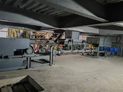
Charging & Feeding System: Charging systems distribute raw materials around the electrodes through gravity or mechanical feeding arrangements. The configuration is selected according to material properties, furnace geometry, and required feeding rate.
Tapping System: Tapping arrangements provide controlled removal of molten metal and slag. Water-cooled components, tapping equipment, mud guns, drills, and related systems can be configured according to furnace design and tapping practice.
Key Features
Closed or Semi-Closed Furnace Options: Gas collection arrangements can be configured to capture furnace off-gas for cleaning, energy recovery, or further process utilization where required by the process design.
Engineered Secondary Electrical Circuit: Busbar geometry and conductor arrangement are designed according to the required current level, electrical impedance, phase balance, and furnace layout.
Integrated Cooling Systems: Water-cooled components can be incorporated into electrode holders, roof structures, shell panels, bus systems, and other areas where controlled thermal management is required.
Electrode Position Control: Real-time electrical measurements can be integrated with the electrode regulation system to adjust electrode position according to changing furnace operating conditions.
Hydraulic Power Unit: Modular hydraulic systems can be configured for electrode lifting, clamping, and other furnace movements, with control functions matched to the selected automation architecture.
Process-Oriented Furnace Design: Furnace dimensions, electrode arrangement, electrical capacity, refractory construction, charging system, cooling system, and gas handling can be engineered around the selected raw material and target product.
Technical Specifications
|
Parameter |
Reference Range |
Unit |
|
Transformer Capacity |
5 - 120 |
MVA |
|
Secondary Voltage |
80 - 320 |
V |
|
Secondary Current |
10,000 - 150,000 |
A |
|
Electrode Diameter |
600 - 1,800 |
mm |
|
Furnace Shell Diameter |
4.0 - 16.5 |
m |
|
Specific Energy Consumption for FeSi75 |
8,200 - 8,800 |
kWh/t |
|
Cooling Water Flow Rate |
250 - 2,500 |
m3/h |
|
Cooling Water Pressure |
0.3 - 0.5 |
MPa |
Applications
Silicon Metal Production: SAF systems can be configured for silicon metal production using quartz or other silicon-bearing feedstocks together with carbonaceous reducing materials. Furnace power, electrode configuration, charging strategy, and gas-handling requirements are determined according to the target production grade and process route. Operating references generally fall in the 24 to 33 MVA range with target silicon purities of at least 98.5% for specified process configurations.
Ferrosilicon Production: SAF systems are used for the reduction and smelting of silicon-bearing materials to produce ferrosilicon grades such as FeSi75 and FeSi65. Electrical power, burden composition, electrode operation, and furnace geometry are selected according to the required product grade and production capacity.
Silicomanganese and High-Carbon Ferromanganese: SAF technology can be applied to manganese-bearing feedstocks for the production of silicomanganese and high-carbon ferromanganese. Furnace design should be matched to ore chemistry, reductant characteristics, target alloy grade, and required production rate.
Ferronickel Production: For ferronickel production, SAF systems can form part of a pyrometallurgical process route such as rotary kiln-electric furnace processing. Furnace configuration depends on laterite ore characteristics, pre-reduction conditions, feed temperature, electrical capacity, and target product specifications.
Calcium Carbide: Closed-type SAF configurations can be used for calcium carbide production from lime and carbonaceous raw materials. The process requires a high-temperature reaction environment, with furnace design and electrical parameters selected according to the production capacity and process route.
Furnace Configuration & Auxiliary Systems
Electrical & Control System
Furnace transformer configured for the required furnace power and secondary electrical conditions
High-current secondary bus system designed according to current level, impedance, and furnace layout
PLC-based control architecture for electrode regulation, electrical monitoring, alarms, interlocks, and operating data collection
SCADA integration where required for process monitoring and production data management
Cooling Water Closed-Loop System
Plate heat exchangers
Circulation pumps
Expansion vessels where required
Flow, pressure, temperature, and conductivity monitoring
Independent cooling circuits for selected furnace components
Automatic protective interlocks according to the system's defined operating limits


Fume Extraction & Gas Cleaning
Depending on furnace type and environmental requirements, the gas treatment system can include:
Furnace hood and gas collection system
Spark arrestors
Gas cooling equipment
Venturi scrubbers where applicable
Baghouse or fabric filtration systems
Dust collection and discharge equipment
Batching & Charging System
Automated weighing hoppers
Conveyors
Skip charging systems
Mechanical feed systems
Dense-phase pneumatic conveying where applicable
Manufacturing & Quality Control
SAF manufacturing involves mechanical fabrication, electrical systems, cooling components, hydraulic systems, refractory interfaces, and control equipment. Quality control covers both individual components and their integration into the furnace system.
Structural Fabrication: Heavy steel furnace components are fabricated according to approved drawings and welding procedures. Non-destructive testing such as ultrasonic testing or magnetic particle inspection can be applied to specified critical welds according to applicable fabrication requirements.
Copper Busbar Machining: High-conductivity copper components are machined to the required dimensions and prepared for electrical connections. Contact surfaces and joints are processed according to the selected electrical design and connection method.
Transformer & Electrical Testing: The furnace transformer and associated electrical equipment undergo appropriate electrical inspections and testing according to the selected equipment specification and applicable standards (including winding resistance, turns ratio, vector group, insulation, and specified electrical tests).
Cooling Component Testing: Water-cooled components and circuits undergo appropriate pressure, leakage, flow, and functional testing before integration into the furnace system.
Pre-Assembly & Functional Checks: Mechanical assemblies such as electrode columns, guide mechanisms, hydraulic cylinders, and other moving systems are checked during shop assembly to verify dimensional alignment, mechanical movement, and interface conditions before shipment.
OEM / Engineering Customization
Metallurgical Process Integration: Electrical operating parameters and furnace configuration matched to raw material chemistry, reductant characteristics, target product grade, and production requirements.
Hearth & Furnace Geometry: Furnace dimensions, electrode arrangement, hearth geometry, and working volume designed according to process requirements and material behavior.
Electrical System Configuration: Transformer capacity, secondary voltage/current, busbar arrangement, electrode system, and control strategy selected according to the required furnace operating range.
Gas Handling & Environmental System: Open, semi-closed, or closed gas-handling configurations considered according to process requirements and local environmental conditions.
Cooling System Design: Cooling circuits and heat-exchange capacity selected according to the thermal load of the furnace components.
Retrofit & Upgrade Engineering: Existing furnace systems assessed for selected modernization requirements, such as electrode regulation, control upgrades, gas-handling modifications, or other defined engineering improvements.
Civil & Structural Interface Engineering: Furnace foundation loads, equipment interfaces, thermal expansion allowances, cooling connections, electrical interfaces, and other plant integration requirements incorporated into the engineering package.
FAQ
As one of the most professional submerged arc furnace manufacturers and suppliers in China, we're featured by quality products and good price. Please rest assured to buy durable submerged arc furnace made in China here from our factory. We also accept customized orders.
Silico Manganese Furnace, Refractory Metal Melting Furnace, High Titanium Slag Smelting FurnacePopular Products